Creating a Robot Configuration
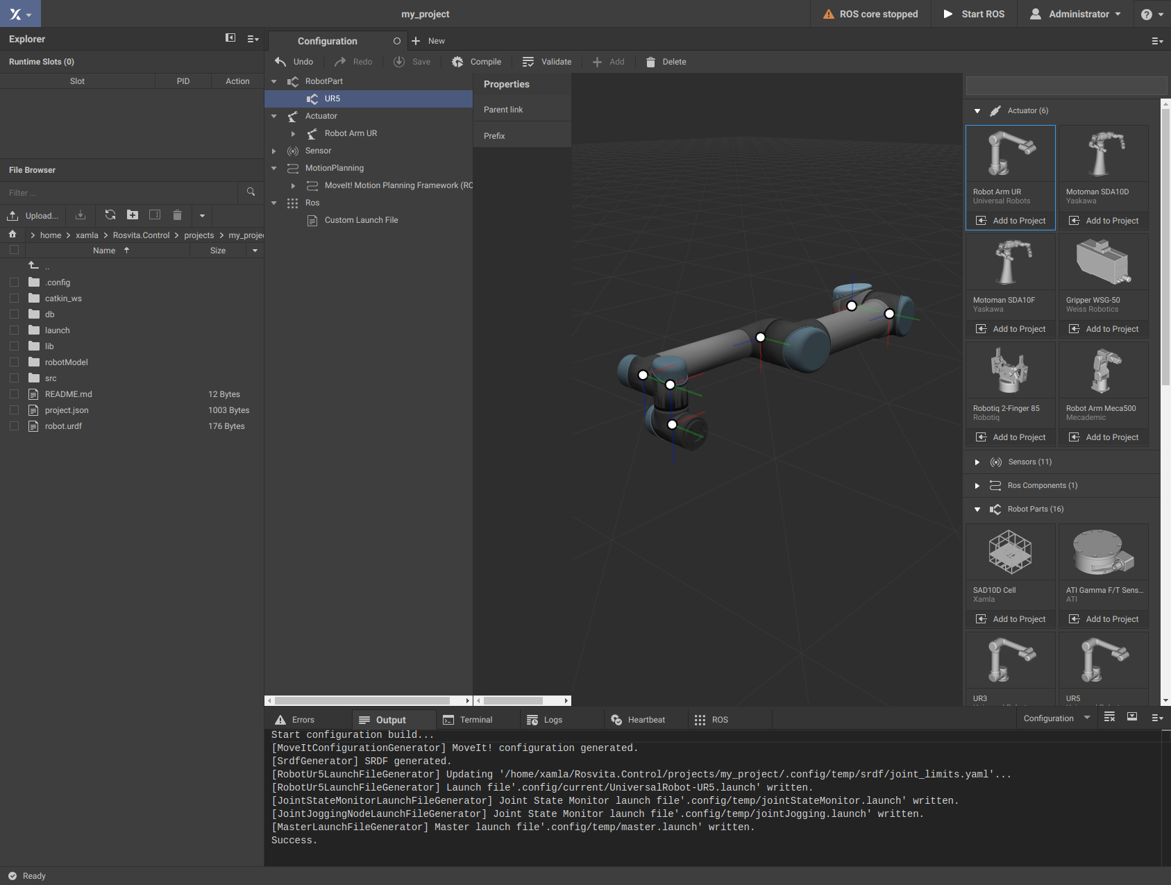
When clicking on the blue-highlighted Xamla symbol in the top left corner and selecting the menu item Configuration, a sidebar for selecting robot parts, actuators, sensors, or other ROS components appears on the right-hand side of the browser (see Fig. 3.1).
Note
If no side bar appears, or in any case of a broken Rosvita web page, refresh the browser cache by pressing Ctrl + F5.
Under the menu item Robot Parts of this sidebar one chooses e.g. the UR5 from Universal Robots (i.e. the corresponding URDF and 3D model). By clicking on the Add to Project button, the corresponding robot part is added to the current configuration. Under the menu item Actuator choose the corresponding actuator (here: Robot Arm UR). The menu bar on the left of the Configuration view lists the individual components of the current configuration. If within this menu bar you click on the previously added robot part UR5, the 3D model of this robot arm including all coordinate systems of the individual joints is displayed in the 3D view. Continuously pressing the left mouse button within the 3D view allows rotation, sustained press of the right mouse button allows moving the scene, and scrolling the mouse wheel will zoom in or out of the 3D scene.

Figure 3.1 Configuration View.
Note
A robot configuration always needs at least one Robot Part (Xacro/URDF robot description, 3D visualization and collision model), as well as the associated Actuator (robot driver).
Note
In the Properties menu of the Actuator (here: Robot Arm UR) the Simulate checkmark is set per default. If you want to configure a real robot, you have to remove this checkmark and enter the IP adress of the robot (see also here).
By clicking on the Save button at the top bar of the Configuration View, the current configuration is saved in the current project, i.e. some of the files in the project folder created before are now filled with life. If you previously selected the UR5 robot arm, in the robotModel folder a new folder part_ur5 will appear. This folder contains the visualization and the collision model of the UR5 robotic arm (.stl files in the subfolder collision and .dae files in the subfolder visual). Furthermore, it contains a part.json file with the MoveIt! configuration of the UR5, as well as .xacro files, from which the URDF (Unified Robot Description Format) for the UR5 will be built. Finally, it includes two additional files CMakeLists.txt and package.xml, which are needed for compiling in a Catkin workspace under ROS. The file robotModel/main.xacro that was already generated when the project was created, will now include the .xacro file of the UR5.
To compile an existing configuration (i.e. building the URDFs from the .xacro files and building the MoveIt! configuration), press the Compile button at the top bar of the Configuration View. In the Output terminal at the bottom of the ROSVITA environment, a message that the start configuration was compiled successfully (similar to the following example message) appears:
Start configuration build...
[MoveItConfigurationGenerator] MoveIt! configuration generated.
[SrdfGenerator] SRDF generated.
[RobotUr5LaunchFileGenerator] Updating '/home/xamla/Rosvita.Control/projects/my_project/.config/temp/srdf/joint_limits.yaml'...
[RobotUr5LaunchFileGenerator] Launch file'.config/current/UniversalRobot-UR5.launch' written.
[JointStateMonitorLaunchFileGenerator] Joint State Monitor launch file'.config/temp/jointStateMonitor.launch' written.
[JointStateMonitorLaunchFileGenerator] Joint State Monitor launch file'.config/temp/jointJogging.launch' written.
[MasterLaunchFileGenerator] Master launch file'.config/temp/master.launch' written.
Success.
In addition, the message not configured next to the warning triangle on the top right is replaced by the message ROS core stopped.
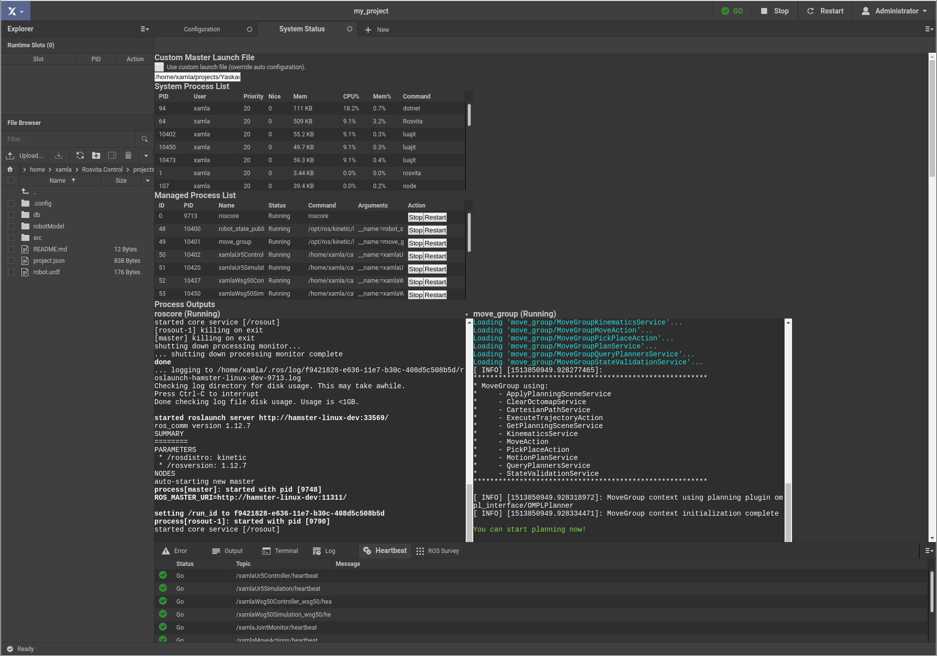
Now, you can start ROS by pressing the button Start ROS in the top bar. The roscore, the robot_state_publisher, the move_group, the xamlaJointMonitor, and several other nodes are started. An overview of the started processes can be obtained by clicking on the blue-highlighted Xamla symbol and selecting the menu item Monitoring there. If everything works fine, after a few seconds a green GO replaces the warning message on the top right and the path planning can begin.

Figure 3.2 Monitoring View
If instead the message Heartbeat failure appears next to the warning triangle and stays there for more than a few seconds, clicking on this warning opens the overview of the system status, i.e. of all processes that have been started. Moreover, hovering above this warning shows the status (GO or NOGO) of all nodes. This individual node status can also be seen when looking at the heartbeat output in the bottom pane. By clicking on the Restart button in the top bar, which now replaces the Start ROS button, ROS will be restarted. If that does not resolve the warning message, you can also restart individual crashed processes in the Managed Process List by clicking the Start button next to the corresponding process. In addition, the outputs and error messages of all started processes can be viewed in detail in the current system status (Monitoring) view. Often, also the Logs output pane gives helpful indications of failure causes.